Product
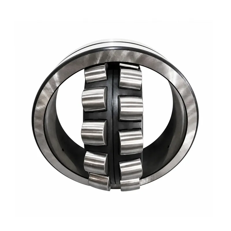
Self-aligning roller bearings
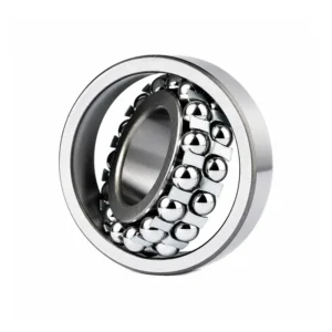
Self-aligning roller bearings are double-row spherical roller bearings . The outer ring raceway has a spherical structure with two rows of symmetrical spherical rollers, providing self-aligning capability.
Product Details
Product Introduction
Self-aligning roller bearings are double-row spherical roller bearings . The outer ring raceway has a spherical structure with two rows of symmetrical spherical rollers, providing self-aligning capability. This allows for a 1.5~2.5° tilt between the inner and outer rings , compensating for coaxiality deviations such as shaft deflection, frame deformation, and installation misalignment. They are designed for extremely high radial loads and can also withstand moderate bidirectional axial loads. They offer strong shock and vibration resistance, making them suitable for heavy-duty vibration applications. Their limiting speed is lower than that of self-aligning ball bearings. Two types of inner bores are available:
- Cylindrical hole: Directly mounted on the stepped shaft;
- The conical bore (suffix K, taper 1:12; K30=1:30 large taper) is paired with a locking sleeve/removal sleeve for easy installation of the optical shaft and adjustment of radial clearance.
Common suffixes:
- CA: Brass solid cage;
- CC: Stamped steel cage, internally optimized;
- W33: Outer ring with oil groove + 3 lubrication holes for easy continuous oil replenishment; Standard: GB/T288-2013, ISO international standard.
Application Scenarios
Heavy-duty, vibrating, shaft-bending, and difficult-to-align equipment:
- Mining equipment: crushers, ball mills, screening machines
- Metallurgical equipment: rolling mills, roller conveyors
- Conveyors: Heavy-duty belt conveyors, bucket elevators
- Papermaking machinery, cement equipment, centrifuges
- Fans (large industrial fans), water pumps
- Vibrating screen, tunnel boring equipment, gearbox
Not recommended for high-speed, light-load conditions (self-aligning ball bearings should be preferred).
Installation Method
Cylindrical bore self-aligning roller bearing
1.Clean the journal and bearing housing bore, remove burrs and rust, and measure the mating dimensions;
2.Apply lubricant to the mating surfaces;
3.Small interference fit: Press machine + copper bushing, only press the inner ring end face for shaft installation; press the outer ring end face for installation into bearing housing, and strictly prohibit striking the rollers and cage ;
4.Large interference fit: Hot charge, heat to 80–120℃, open flame is prohibited, temperature should not exceed 130℃ to prevent tempering failure;
5.After the bearing is in place, do not immediately tighten the end cover. Manually rotate the shaft several times to allow the bearing to automatically align before tightening and fixing it.
6.Add lubricating grease, run under no-load test, and monitor temperature rise and vibration.
Conical hole (K type) + locknut installation
1.Insert the locking sleeve into the optical shaft and push the bearing into the locking sleeve;
2.Rotate the lock nut to push the bearing, and control the interference by reducing the radial clearance (this is very important; if it is too tight, the bearing may overheat and burn out).
3.After installation, radial clearance must be measured to confirm that the clearance meets the standard.
4.Locking anti-loosening washer/anti-loosening nut.
The core principle of installation is that force should not be transmitted through the rollers to avoid damaging the raceways.
Usage & Maintenance Precautions
1.Self-alignment limit : Maximum allowable tilt is 1.5~2.5°, exceeding the angle will drastically shorten the lifespan;
2.Load characteristics : Primarily radial under heavy loads, can withstand medium axial loads in both directions, but not suitable for pure large axial loads.
3.Lubrication is crucial : heavy-duty rollers experience high friction and require adequate and clean lubrication; the W33 oil groove model allows for online grease replenishment; aged grease and impurities can quickly cause bearing failure.
4.Temperature control : The recommended long-term operating temperature is below 100℃; the temperature for hot-fitting should not exceed 130℃.
5.Clearance selection : Standard CN clearance; C3 for high temperature, large interference, and vibration conditions; C4 for heavy impact loads;
6.Storage : Store in a dry, dark place, do not stack or compress; wear gloves when handling to prevent corrosion from sweat.
7.Fit selection : Use a tight fit for the inner ring; use a loose fit for the outer ring when compensating for movement.
8.Impact is prohibited : Knocking or heavy object impact will cause indentations on the rollers and raceways, and excessive vibration during operation.
Commonly Used Model Dimensions Table (GB/T288-2013, Unit: mm)
Fields: Model | d Inner Diameter | D Outer Diameter | B Width | r Minimum Chamfer | Cr Basic Dynamic Load (kN) | Cor Basic Static Load (kN) | Grease-lubricated Limiting Speed (rpm) | Reference Weight (kg)
Suffix K = conical bore; W33 outer ring oil groove/oil hole; CC/CA cage structure
213 Series (Narrow cross-section, compact space)
| Model | d | D | B | r | Cr | Cor | Grease Rotation Speed | Weight (kg) |
| 21305 | 25 | 62 | 17 | 1.0 | 44.2 | 44.8 | 5300 | 0.27 |
| 21306 | 30 | 72 | 19 | 1.0 | 57.2 | 58.5 | 4500 | 0.39 |
| 21307 | 35 | 80 | 21 | 1.0 | 69.5 | 72.2 | 3800 | 0.52 |
| 21308 | 40 | 90 | 23 | 1.0 | 86.5 | 90.8 | 3400 | 0.71 |
| 21309 | 45 | 100 | 25 | 1.0 | 102 | 108 | 3000 | 0.96 |
| 21310 | 50 | 110 | 27 | 1.5 | 122 | 130 | 2700 | 1.26 |
| 21311 | 55 | 120 | 29 | 1.5 | 142 | 152 | 2400 | 1.62 |
| 21312 | 60 | 130 | 31 | 1.5 | 162 | 175 | 2200 | 2.04 |
222 series (general-purpose wide type, most commonly used in the market)
| Model | d | D | B | r | Cr | Cor | Grease Rotation Speed | Weight (kg) |
| 22205 | 25 | 52 | 18 | 1.0 | 36.8 | 36.8 | 8000 | 0.177 |
| 22206 | 30 | 62 | 20 | 1.0 | 51.8 | 55.0 | 6700 | 0.283 |
| 22207 | 35 | 72 | 23 | 1.0 | 70.2 | 79.0 | 5600 | 0.437 |
| 22208 | 40 | 80 | 23 | 1.0 | 79.0 | 88.5 | 5000 | 0.524 |
| 22209 | 45 | 85 | 23 | 1.0 | 82.8 | 95.2 | 4500 | 0.571 |
| 22210 | 50 | 90 | 23 | 1.0 | 86.0 | 102 | 4300 | 0.614 |
| 22211 | 55 | 100 | 25 | 1.5 | 114 | 138 | 3800 | 0.897 |
| 22212 | 60 | 110 | 28 | 1.5 | 142 | 172 | 3400 | 1.21 |
| 22213 | 65 | 120 | 31 | 1.5 | 172 | 208 | 3000 | 1.64 |
| 22214 | 70 | 125 | 31 | 1.5 | 182 | 222 | 2800 | 1.75 |
| 22215 | 75 | 130 | 31 | 1.5 | 188 | 235 | 2600 | 1.85 |
| 22216 | 80 | 140 | 33 | 2.0 | 212 | 268 | 2400 | 2.30 |
| 22217 | 85 | 150 | 36 | 2.0 | 242 | 308 | 2200 | 2.90 |
| 22218 | 90 | 160 | 40 | 2.0 | 280 | 358 | 2000 | 3.70 |
| 22219 | 95 | 170 | 43 | 2.0 | 322 | 415 | 1900 | 4.55 |
| 22220 | 100 | 180 | 46 | 2.0 | 370 | 480 | 1800 | 5.40 |
223 Series (Extra-wide, the first choice for heavy-duty impact resistance)
| Model | d | D | B | r | Cr | Cor | Grease Rotation Speed | Weight (kg) |
| 22308 | 40 | 90 | 33 | 1.5 | 132 | 138 | 3800 | 1.02 |
| 22309 | 45 | 100 | 36 | 1.5 | 158 | 170 | 3400 | 1.37 |
| 22310 | 50 | 110 | 40 | 2.0 | 192 | 208 | 3000 | 1.86 |
| 22311 | 55 | 120 | 43 | 2.0 | 228 | 248 | 2800 | 2.40 |
| 22312 | 60 | 130 | 46 | 2.0 | 260 | 285 | 2400 | 3.02 |
| 22313 | 65 | 140 | 48 | 2.0 | 288 | 320 | 2200 | 3.68 |
| 22314 | 70 | 150 | 51 | 2.0 | 325 | 365 | 2000 | 4.45 |
| 22315 | 75 | 160 | 55 | 2.0 | 368 | 415 | 1900 | 5.40 |
| 22316 | 80 | 170 | 58 | 2.0 | 412 | 465 | 1700 | 6.45 |
| 22317 | 85 | 180 | 60 | 2.5 | 450 | 520 | 1600 | 7.45 |
| 22318 | 90 | 190 | 64 | 2.5 | 500 | 578 | 1500 | 8.70 |
| 22319 | 95 | 200 | 67 | 2.5 | 542 | 640 | 1400 | 10.10 |
| 22320 | 100 | 215 | 73 | 2.5 | 620 | 730 | 1300 | 12.20 |
230 Series (Thin cross-section, large outer diameter, space-constrained heavy-duty)
| Model | d | D | B | r | Cr | Cor | Grease Rotation Speed | Weight (kg) |
| 23024 | 120 | 180 | 46 | 2.0 | 310 | 465 | 1700 | 4.10 |
| 23026 | 130 | 200 | 52 | 2.0 | 370 | 560 | 1500 | 5.60 |
| 23028 | 140 | 210 | 53 | 2.0 | 405 | 620 | 1400 | 6.20 |
| 23030 | 150 | 225 | 56 | 2.1 | 450 | 695 | 1300 | 7.50 |