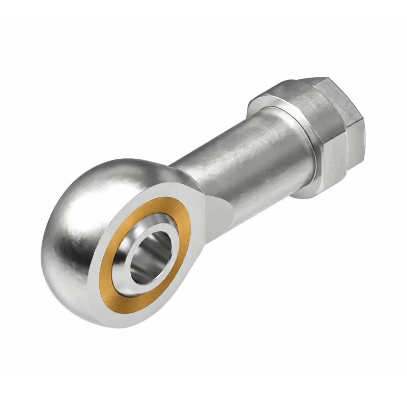
Product
Spherical Plain Bearing
The rod end spherical plain bearing, commonly known as a fisheye bearing, is composed of a forged steel rod body and a spherical plain bearing. It has self-aligning capability, can compensate for installation misalignment errors, and is suitable for low-speed oscillating linkage structures.
Product Details
Product Introduction
The rod end spherical plain bearing, commonly known as a fisheye bearing, is composed of a forged steel rod body and a spherical plain bearing. It has self-aligning capability, can compensate for installation misalignment errors, and is suitable for low-speed oscillating linkage structures.
- SI / SIL: Internal thread (female thread) , the rod body is a threaded hole, and the screw is screwed into the hole; SI is right-hand positive thread, SIL is left-hand reverse thread, used in pairs to quickly adjust the overall length of the pull rod.
- SA / SAL: External thread (male thread) , the rod body has an integrated external thread; SA is right-hand positive thread, SAL is left-hand reverse thread, directly screwed into the frame nut for fixation.
The two structures are each divided into two main categories:
1.T/K (ES) steel-to-steel type: with lubrication hole for grease filling, heavy-duty and impact resistant.
2.Type C, self-lubricating: PTFE lining, maintenance-free, do not use grease. 2RS suffix: double-sided rubber sealing ring, dustproof and moisture-proof.
Stress: Primarily bears radial loads, with a small amount of axial load; suitable only for low-speed oscillation, not for continuous high-speed rotation.
Precautions
1.Thread distinction: SI for internal thread, SA for external thread; L indicates left-hand reverse thread. This can be confusing when ordering; please confirm both thread type and direction of rotation.
2.For steel-to-steel T/K type, apply grease regularly; for self-lubricating C type, grease is strictly prohibited, as it will damage the PTFE liner and cause direct failure.
3.The bearing’s allowable swing angle must not be exceeded; excessive swing angle will cause rapid wear on the spherical surface.
4.Do not strike the bearing spherical surface. Clamp only the shaft, not the outer ring of the ball head, to prevent damage from impacts to the steel balls/spherical surface.
5.After installation under vibration conditions, be sure to install anti-loosening nuts to prevent the threads from loosening and coming off.
6.The 2RS sealed version is suitable for dusty and humid environments; the open version is suitable for clean indoor environments.
7.Store in a moisture-proof and rust-proof manner to protect the threads and prevent damage from impacts.
Installation Method
1.Cleaning: Clean the pins, bearing inner holes, and threads, remove burrs and metal filings, and check the threads for damage.
2.Assembly plan:
- SI+SIL (Internal Thread Pairing): The two screws are screwed into SI (positive thread) and SIL (negative thread) respectively. By rotating the pull rod body, the length of the connecting rod can be adjusted as a whole, and the locking cap can be adjusted.
- SA+SAL (external thread, positive and negative pairing): Directly screw the SA and SAL screws into the fixing plate nut, rotate the rod body to adjust the overall length, and tighten the nut to fix it.
3.Pin assembly: Insert the pin smoothly into the inner hole of the bearing ball head, without tilting or hammering.
4.Axial limiting: retaining rings are installed at both ends to prevent the pin from coming out.
5.Test run: Manually push and pull the connecting rod to confirm that the swing is smooth and there is no jamming.
6.Lubrication and maintenance: For the T/K model, add grease through the grease fitting; for the C model, which is self-lubricating, no grease is required.
Usage Locations (Application Scenarios)
Cylinder connecting rods, construction machinery, agricultural machinery, automation equipment, robot linkages, testing fixtures, stage lifting mechanisms, automotive suspension, conveying equipment, hydraulic linkages, and fitness equipment.
Product Model Dimensions Table (SI/SIL internal thread + SA/SAL external thread, unit mm)
d = Bearing inner diameter; G = Thread specification; B = Inner ring width; Dk = Outer diameter of spherical surface; h = Center height; α ≈ Allowable swing angle. For the same specification: SI = SIL (completely identical dimensions); SA = SAL (completely identical dimensions, only thread direction differs).
| inner diameter d | Internal threads: SI (positive) / SIL (negative) | Thread G | B | Dk | h | Swing angle α | External thread (SA) – positive thread / (SAL) – negative thread | Thread G | B | Dk | h | Swing angle α |
| 5 | SI5T/K, SIL5T/K | M5×0.8 | 8 | 13 | 32 | 13° | SA5T/K, SAL5T/K | M5×0.8 | 8 | 13 | 32 | 13° |
| 6 | SI6T/K, SIL6T/K | M6×1.0 | 9 | 16 | 36 | 13° | SA6T/K, SAL6T/K | M6×1.0 | 9 | 16 | 36 | 13° |
| 8 | SI8T/K,SIL8T/K | M8×1.25 | 12 | 19 | 42 | 13° | SA8T/K, SAL8T/K | M8×1.25 | 12 | 19 | 42 | 13° |
| 10 | SI10T/K,SIL10T/K | M10×1.5 | 14 | 22 | 48 | 12° | SA10T/K,SAL10T/K | M10×1.5 | 14 | 22 | 48 | 12° |
| 12 | SI12T/K, SIL12T/K | M12×1.75 | 16 | 26 | 54 | 12° | SA12T/K, SAL12T/K | M12×1.75 | 16 | 26 | 54 | 12° |
| 14 | SI14T/K, SIL14T/K | M14×2.0 | 19 | 29 | 60 | 11° | SA14T/K, SAL14T/K | M14×2.0 | 19 | 29 | 60 | 11° |
| 16 | SI16T/K, SIL16T/K | M16×2.0 | 21 | 32 | 64 | 11° | SA16T/K, SAL16T/K | M16×2.0 | 21 | 32 | 64 | 11° |
| 18 | SI18T/K, SIL18T/K | M18×1.5 | 23 | 36 | 72 | 10° | SA18T/K, SAL18T/K | M18×1.5 | 23 | 36 | 72 | 10° |
| 20 | SI20T/K, SIL20T/K | M20×2.0 | 25 | 40 | 78 | 10° | SA20T/K, SAL20T/K | M20×2.0 | 25 | 40 | 78 | 10° |
| 22 | SI22T/K, SIL22T/K | M22×1.5 | 28 | 44 | 84 | 9° | SA22T/K, SAL22T/K | M22×1.5 | 28 | 44 | 84 | 9° |
| 25 | SI25T/K, SIL25T/K | M24×2.0 | 31 | 47 | 94 | 9° | SA25T/K, SAL25T/K | M24×2.0 | 31 | 47 | 94 | 9° |
| 30 | SI30T/K, SIL30T/K | M30×2.0 | 37 | 62 | 110 | 8° | SA30T/K, SAL30T/K | M30×2.0 | 37 | 62 | 110 | 8° |
| Model (Orthodontic SA) | Model (Reverse SAL) | inner diameter d | External thread G | B | Dk | Center height h | Swing angle α |
| SA5T/K | SAL5T/K | 5 | M5×0.8 | 8 | 13 | 32 | 13° |
| SA6T/K | SAL6T/K | 6 | M6×1.0 | 9 | 16 | 36 | 13° |
| SA8T/K | SAL8T/K | 8 | M8×1.25 | 12 | 19 | 42 | 13° |
| SA10T/K | SAL10T/K | 10 | M10×1.5 | 14 | 22 | 48 | 12° |
| SA12T/K | SAL12T/K | 12 | M12×1.75 | 16 | 26 | 54 | 12° |
| SA14T/K | SAL14T/K | 14 | M14×2.0 | 19 | 29 | 60 | 11° |
| SA16T/K | SAL16T/K | 16 | M16×2.0 | 21 | 32 | 64 | 11° |
| SA18T/K | SAL18T/K | 18 | M18×1.5 | 23 | 36 | 72 | 10° |
| SA20T/K | SAL20T/K | 20 | M20×2.0 | 25 | 40 | 78 | 10° |
| SA22T/K | SAL22T/K | 22 | M22×1.5 | 28 | 44 | 84 | 9° |
| SA25T/K | SAL25T/K | 25 | M24×2.0 | 31 | 47 | 94 | 9° |
| SA30T/K | SAL30T/K | 30 | M30×2.0 | 37 | 62 | 110 | 8° |